
The locomotion mechanism determines how chassis actions are recorded. Two-wheel differential drive, speed 1.5 m/s, climbing slope 5°. Positioning accuracy ±10 mm / ±3°. Four-wheel steering-drive, two-wheel differential drive, and in-place turning radius are three different ground-level statements and cannot be rewritten into one another. A speed range and a single speed value are also not interchangeable.
Mobility method
If the demonstration includes cart pushing, line following, or workstation changes, the record must include a chassis channel: at least velocity or pose, plus a timestamp. Recording only the arm makes mobile manipulation samples incomplete. Recording only the chassis leaves tabletop manipulation samples missing the arm. According to the robotic arm parameter table, the single-arm degrees of freedom for model RM75-B-V is 7. The product page does not publish the total degrees of freedom for the whole machine; do not fill in 17 or 20. How to split the channels should follow this degrees-of-freedom statement or the description of the chassis on this page.
Slope grade, positioning error, ultrasonic, and safety edge only become site conditions on pages where they are stated. Do not infer on pages where they are absent that "since it can move, it has the same positioning accuracy." For the wheeled lift dual-arm teleoperation body page, the ground-related sentences are exactly the ones quoted above.
Safe speed is not the maximum speed on the table. The 1.5 m/s or 0.1–1.5 m/s on the table is the publicly stated motion capability; teaching can be slower. Slower does not require changing the specification, but it must be written into the experiment record so that later readers do not assume the samples were collected at maximum speed.
How to Use This Page in This Version
How the chassis moves determines whether the demonstration is mobile manipulation. Two-wheel differential drive, speed 1.5 m/s, climbing 5°. Positioning accuracy ±10 mm / ±3°. Copy this sentence into the ground section of the experiment plan; do not rewrite it as "omnidirectional" or "differential" unless the original sentence used that term. Four-wheel steering and four-wheel drive is not colloquial for differential drive, in-place rotation radius is not the turning radius of a differential vehicle, and a single 1.5 m/s is not shorthand for 0.1–1.5 m/s.
The recording format should include at least: timestamp, base velocity or pose, whether rotation is permitted, and emergency-stop state. If only arm joint motion operation samples are recorded, it is impossible to distinguish "the arm is moving" from "the base is moving" afterward. If only base tabletop operation samples are recorded, the operation itself is missing. The single-arm degrees of freedom for robotic arm model RM75-B-V in the parameter table is 7. The product page does not publish the total system degrees of freedom; do not fill in 17 or 20. If the degrees of freedom on this page do not include the base, the base channel must be listed separately rather than folded into the degrees-of-freedom integer.
The upper limit of speed is not the capture speed. The capture speed is written in the operating-condition column of the experiment record and may be lower than the publicly stated motion capability. The operating-condition column is not written back to the product page, nor is a single slow experiment described as a specification limited to that slow speed.
Slope grade, positioning accuracy, safety edge, and ultrasonic only become mobility conditions on pages where they appear. The wheeled lift dual-arm teleoperation body does not have these rows, so do not borrow 5° or ±10 mm from the lift model. If these rows exist, write them into site confirmation, not into algorithm advantages. /product-body-lift.html is used to verify whether these rows are actually present.
Line-by-Line Verification
Degrees of freedom. The single-arm degrees of freedom for the robotic arm model RM75-B-V in the parameter table is 7. The product page does not publish the total degrees of freedom of the whole machine; do not fill in 17 or 20. This row only states the number of joints and body parts that have already been made public. It does not evaluate intelligence, and it does not automatically include the waist, legs, neck, or whole-machine total that are not named on the page. When writing the action vector, only build channels for the body parts listed in the row; body parts not listed remain blank. Do not write blanks as 0, because 0 will be treated by training scripts as a real angle. Do not fill in the degrees-of-freedom integer from another device after this row to make up the numbers. If the master-slave joint order is not given on the page, mark it as pending written configuration confirmation; do not number it yourself. A chassis that is not within the degrees of freedom should be recorded as a separate channel. The action vector only builds channels for the body parts named in this row; unnamed body parts are left blank, not filled with 0.
Load and quality. The rated payload of a single arm is 5 kg. The 8 kg in the parameter table is the self-weight of a single arm. The dual-arm rated payload of 8 kg previously written on the cover conflicts with the parameter table; the parameter table takes precedence. The overall mass of approximately 80 kg is the total system mass. The numbers in this row must be read aloud with their subjects: rated, self-weight, total system mass, envelope, friction, or gripping force. If the subjects differ, they cannot be merged into a single number, nor can any conversion not provided on the page be performed. If the actual objects on site are heavier, the specification cannot be changed retroactively; a larger specification also does not prove that every grasping method reaches that limit. The tool mass is undetermined, so do not write the arm's rated payload as the graspable object mass. The acceptance form retains the original units. Payload does not determine the steering method. During acceptance, read the subject first and then the number; if the subjects are inconsistent, split them into two rows.
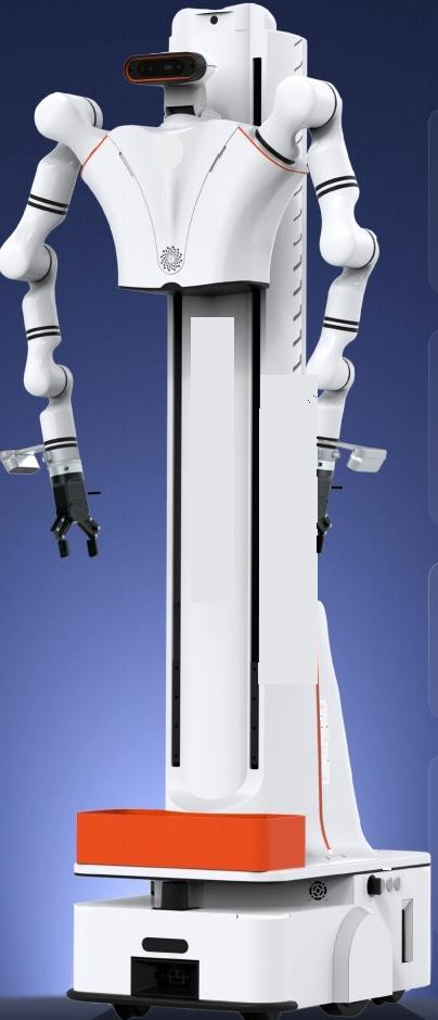
Form and Dimensions. Model RMC-AIDAL. Stowed dimensions 640 × 450 × 1780 mm. Base 640 × 450 × 250 mm. This row covers form or structural dimensions, used to check doorways, elevators, tabletops, or transport. It is not operating height and not arm reach. Do not add it to the vertical range. If the diagram shows protrusions, antennas, or a person's standing position not listed in this row, note separately that they are not part of the specification. If weight appears in an adjacent row, do not include it in the dimension sentence. The form width is used for passing through doorways, not for calculating rotation radius. Doorways, elevators, and transport are checked against form only; do not treat this row as operating height.
Operating Range. Lift travel 900 mm, vertical working range 0–2.4 m (also written as 0–2400 mm in the table). Single-arm reach 633 mm. Single-side overhang beyond the base 790 mm; the source does not specify a unit at that point, but it appears alongside millimeters in the same sentence, so write 790 mm externally and retain this note. This row describes the range the hand or lift can reach. The definitions must follow the source sentence: vertical working range, reach, motion radius, or travel — these cannot be added together or renamed. If "excluding end effector" is stated, it must remain in the figure caption. When the source does not specify a unit, retain the "unit not specified" note; do not remove it for tidiness. Operating height does not substitute for ground mobility capability. The figure caption retains the range definitions from the source sentence, as well as the terms "excluding end" or "unit not specified."
Motion. Two-wheel differential drive, speed 1.5 m/s, climbing 5°. Positioning accuracy ±10 mm / ±3°. This row describes how the ground or main arm moves. Four-wheel four-drive, differential drive, in-place rotation radius, and rotational speed are terms for different mechanisms and cannot be substituted for each other. Published speed is a capability, not a recommended teaching speed; teaching can be slower, but the slower speed is written into the experimental conditions and is not written back into the specification. Pages that do not specify climbing or positioning should not borrow from other pages. This is the main row for ground speed or rotational speed; mechanism terms must not be substituted. The teaching speed can be lower, but the lower speed is written into the conditions and does not change the published capability in this row.
Power supply. The battery is lithium iron phosphate DC 48V 20Ah. This document dated 2026-08-03 does not state the runtime in hours. Do not fill in approximately 6 hours, and do not rewrite it as 48V 31Ah or approximately 4 hours. This line retains only the electrical terms that appear on the page: voltage, capacity, runtime, charging, current, or power. If "hours" is not present, write "runtime not specified"; do not fill in the blank with hours from an adjacent page. Do not rename charging time as runtime. Rated and maximum values must be listed separately. Keep "approximately" for approximate values. Do not sum the ampere-hours of multiple devices and attribute the total to a single device's battery. Runtime does not prove that the device can operate continuously at the tabled speed for that duration. Hours, charging, or current that do not appear should remain as not specified and must not be copied in from an adjacent page.
Perception and Compute. Main controller Nvidia Jetson AGX Orin 64G, plus a 1T solid-state drive. Standard vision: D435 ×1, wide-angle camera ×2, voice module ×1. If the cover states 3 depth channels plus 2 wide-angle channels, which conflicts with the list, the specification follows the list. D435 row: ideal ranging 0.3–3 m; depth ≤1280×720, ≤90 fps; RGB 1920×1080, 30 fps; field of view 69°×42°; rolling shutter. Navigation separately lists depth camera ×1, IMU + encoder ×1, LiDAR ×1, safety edge ×1, ultrasonic ×2. This row inventories the items explicitly stated in sensors, compute, or communications, and retains the terms standard, standard-equipped, optional, and optional-order. Unchecked optional items do not count. When the cover conflicts with the list, cite the list while not pretending the cover statement does not exist. Head-mounted devices and gloves do not enter this row. Processors, storage capacity, or camera channel counts not written out must not be drawn into the system diagram. LiDAR and ultrasonic, if present in the list, are navigation conditions, not speed values. Optional sensors not purchased do not enter this data dictionary.
End Effector. The recommended configuration lists gripper CTAG2F90-D ×2. The standard configuration quantity table does not include a gripper. RMG22-65 is a separate product page. This row describes where contact or grasping occurs. Quick-change, compatible, and recommended are not models already included in the box. The ring fixture on the main arm is not an end gripper. Force, travel, and payload remain as written in their respective rows and are not merged into a single system metric just because they are mounted on a particular body. Where flange and protocol mapping are not provided, write "to be confirmed," not "plug and play." The end effector does not change the base drive type. "Supports" or "compatible" without a model number cannot be treated as delivered.
Boundary. The standard configuration lists robotic arm RM65-B-V ×2, while the robotic arm parameter table lists model RM75-B-V. Keep both model numbers; lock them before ordering; do not collapse them into one. This row is a deliberate boundary on the page: another model, another column, another product page, or an interface that still requires project confirmation after modularization. The boundary is not a defect note; it prevents verbally buying two pages as one. When writing a proposal, copy the boundary into "not included in this order." If equipment not included is added later, open a new configuration sheet; do not go back and change the body name in old samples. Do not borrow slope grade or positioning from another unit. Equipment within the boundary must be ordered separately; do not rename old samples to say it is already included.
Configuration column. The recommended configuration is RM75-B-V ×2, two-wheel differential chassis ×1, gripper CTAG2F90-D ×2. Teleoperation options are servo teleoperation, backpack teleoperation, and mobile teleoperation, which are not included in the standard configuration quantity table. This row distinguishes standard, recommended, and optional. Recommended and optional items are not delivered unless checked. When the standard row and the parameter table row are inconsistent, keep both rows and use "locked for this order" to indicate which one is actually delivered, rather than crossing out one row in the order without signing off. Price and lead time are not written into this row's restatement. If the mobile mechanism belongs to the recommended chassis, the order must specify whether this order is for that chassis. Unchecked recommended and optional items are written as not delivered on the order.
Excerptable. Attachments may copy: RMC-AIDAL; 640×450×1780 mm; approximately 80 kg; lift 900 mm; vertical 0–2.4 m; reach 633 mm; rated 5 kg; self-weight 8 kg; repeatability ±0.05 mm; differential 1.5 m/s; slope 5°; positioning ±10 mm / ±3°; Orin 64G + 1T SSD; lithium iron phosphate DC 48V 20Ah, hours not given. This row is the type that can be pasted into an attachment: with a subject, with units, and traceable to the source sentence on the product page. When pasting, retain "approximately," "excluding," "not given," "optional," and "recommended." Do not convert and keep only the result. If the same number has different meanings on two pages, write it as two rows in the attachment. Do not mix test protocols into specification excerpts. Write speed as the original range or single value; do not change it to "fastest." When pasting into an attachment, paste the words "approximately," "excluding," and "optional" along with the values.
Do not write. Do not write 17 degrees of freedom for the full machine, do not write 650×512×1700 mm, approximately 120 kg, lifting 0.3 m, vertical 0–2.1 m, speed 0.1–1.0 m/s. Do not write 8 kg as the rated payload. Do not write battery life in hours. This row is a negative statement for review purposes. It does not describe what the equipment can do; it only prevents hours, degrees of freedom, load subjects, or cover slogans from adjacent pages from being written in. If a negative statement is hit, revert to the original sentence on the product page; do not interpret it as "close enough." Success rates from external papers and total hours not publicly disclosed on this site must likewise not be written in. Do not conflate 0.1–1.5 m/s, 1.5 m/s, and rotational speed in RPM as the same velocity. If a manuscript search hits a negative statement, revert to the original sentence on the product page.
| Projects | Public-Facing Positioning of This Page |
|---|---|
| Degrees of Freedom | In the robotic arm parameter table, model RM75-B-V has 7 degrees of freedom per arm. The product page does not publish the total degrees of freedom for the whole unit; do not fill in 17 or 20. |
| Load and Mass | Single-arm rated payload 5 kg. The 8 kg in the parameter table is the single-arm self-weight. The cover previously stated a dual-arm rated payload of 8 kg, which conflicted with the parameter table; the parameter table takes precedence. The total unit weight of approximately 80 kg is the overall mass. |
| Form Factor and Scale | Model RMC-AIDAL. Folded dimensions 640 × 450 × 1780 mm. Chassis 640 × 450 × 250 mm. |
| Operating Range | Lifting stroke 900 mm, vertical working range 0–2.4 m (also written as 0–2400 mm in the table). Single-arm reach 633 mm. Single-side overhang beyond the chassis is 790 mm; the original text did not specify a unit at that point, but since it appears alongside millimeters in the same sentence, it is written externally as 790 mm with this note retained. |
| Motion | Two-wheel differential drive, speed 1.5 m/s, climbing slope 5°. Positioning accuracy ±10 mm / ±3°. |
| Power | The battery is lithium iron phosphate DC 48V 20Ah. This document dated 2026-08-03 does not state battery life in hours. Do not add approximately 6 hours, and do not rewrite it as 48V 31Ah or approximately 4 hours. |
| Perception & Compute | Main controller Nvidia Jetson AGX Orin 64G, with an additional 1T solid-state drive. Standard vision configuration is D435 ×1, wide-angle cameras ×2, voice module ×1. If the cover states 3 depth channels plus 2 wide-angle channels, this conflicts with the list; the specifications follow the list. D435 row: ideal ranging 0.3–3 m; depth ≤1280×720, ≤90 fps; RGB 1920×1080, 30 fps; field of view 69°×42°; rolling shutter. Navigation separately lists depth camera ×1, IMU + encoder ×1, LiDAR ×1, safety edge ×1, ultrasonic ×2. |
| End Effector | The recommended configuration lists gripper CTAG2F90-D ×2. The standard configuration quantity table does not include a gripper. RMG22-65 is a separate product page. |
| Boundary | The standard configuration lists the robotic arm as RM65-B-V ×2, while the robotic arm parameter table lists the model as RM75-B-V. Both model numbers are retained; lock one before placing the order — do not collapse them into a single number. |
| Configuration Panel | Recommended configuration is RM75-B-V ×2, two-wheel differential chassis ×1, gripper CTAG2F90-D ×2. Teleoperation options are servo teleoperation, backpack teleoperation, and mobile teleoperation; these are not included in the standard configuration quantity table. |
| Excerptable | Attachment copy: RMC-AIDAL; 640×450×1780 mm; approximately 80 kg; lifting 900 mm; vertical 0–2.4 m; reach 633 mm; rated 5 kg; self-weight 8 kg; repeatability ±0.05 mm; differential drive 1.5 m/s; slope climbing 5°; positioning ±10 mm / ±3°; Orin 64G + 1T SSD; lithium iron phosphate DC 48V 20Ah, hours not specified. |
| Do not write | Do not write 17 degrees of freedom for the whole unit, and do not write 650×512×1700 mm, approximately 120 kg, lifting 0.3 m, vertical 0–2.1 m, speed 0.1–1.0 m/s. Do not write 8 kg as the rated payload. Do not write battery life in hours. |
Relationship to Public Methods and Adjacent Pages
The locomotion type determines what "chassis motion" means in teleoperation. Four-wheel independent steering with drive can adjust heading laterally and in place, suitable for repositioning between narrow lab benches. A differential chassis steers by varying left and right wheel speeds; its structure differs, and speed and gradeability must be cited separately. The wheeled humanoid's turning radius is a ground-scale measurement of turning around its own axis; it cannot be written as the minimum turning radius of a differential vehicle unless the page defines it that way.
The folding model is specified as four-wheel steering and four-wheel drive. The lift model's chassis is differential drive, speed 1.5 m/s, climbing grade 5 degrees, positioning accuracy ±10 mm / ±3 degrees. The wheeled humanoid gives a turning radius of 690 mm, and both the shoulders and the chassis fit within a 465 mm width. Three sentences describe three ground strategies. Writing 1.5 m/s onto the folding model or the wheeled humanoid is cross-page copying.
For data, chassis speed, angular speed, and the joint angles of the manipulator are different channels. Recording only the arm and not the chassis makes the mobile manipulation demonstration incomplete. Recording only the chassis and not the arm makes the tabletop manipulation demonstration incomplete. When the product page does not provide details of the chassis control interface, the interface is governed by the written configuration; do not invent a topic name in the article.
This article explains the product's publicly disclosed motion parameters and the type of chassis quantities it requires to be retained in the dataset.
Before handing off to a colleague
Mobile testing is carried out in two steps.
The first step is to confirm only the mechanism terms: whether the on-site chassis or main arm is the type described in the original sentence — if not, stop.
Only in the second step do you record velocity, and the recorded value may be below the publicly stated capability, as long as it is noted in the operating conditions column. Do not backfill the speed of a single slow demonstration as a specification. Positioning, slope climbing, ultrasonic, and edge contact: if they are not on the page, do not test whether these items "meet the standard"; you may use the project's own safety requirements, but do not write those requirements as product specifications. The emergency stop test comes before any mobile capture. Mechanism confirmation uses photos plus the original sentence, not a verbal "you know, that kind of wheel." Photos cannot replace the original sentence; the original sentence goes in the photo caption. If the velocity logger shows a higher or lower value, do not modify the product page. If higher and it exceeds the publicly stated capability, stop and check whether the wrong device was recorded; if lower, write it into the operating conditions. Samples after the emergency stop and samples before it go in separate directories. Do not automatically append the first segment after emergency stop recovery to the previous segment.
First, confirm the mechanism terms before recording the speed.
Second, a lower demonstration speed is written into the operating conditions.
Third, do not write operating conditions back into specifications.
Fourth, gradeability and positioning not on the page must not be tested as specifications.
Fifth, emergency stop comes before capture.
Sixth, separate directories before and after emergency stops.
Continue Reading
- 01 Task Boundaries
- 02 Specification Standards
- 03 Degrees of Freedom
- 04 Payload & Self-Weight
- 05 Workspace
- 06 Locomotion Method
- 07 Perception and Computing
- 08 Power Specifications
- 09 Data Recording
- 10 Time Alignment
- 11 End-Effector Boundaries
- 12 Site Constraints
- 13 Configuration Sheet
- 14 Three-Way Comparison
- 15 Literature References
- 16 Master-Slave Workstation
- 17 Acceptable Deliverable Statements
- 18 Prohibited Conflations
- 19 On-Site Deployment
- 20 Evaluation Path
Back to Product Center View this product page
This article was written on October 3, 2026, for selection and specification verification purposes. Device parameters are subject to the product page tables and do not constitute a supply commitment. External papers only illustrate how problems are framed in the industry; their success rates and data scales belong to the original authors' experiments and are not TOBI's measured results. Phone: +86 137 5502 0164.