
Pressing start simultaneously is not a shared clock. If the two-finger parallel gripper RMG22-65 is used together with the head-mounted unit, master arm, and gripper, the configuration sheet must state the master clock, alignment error, and dropped-frame flag. The page does not promise that PPS or serial-port time sync has been used. Powering on the wrist camera and the light ring at the same time is also not time sync.
Time alignment
Each sampling rate is copied from its own page. The recording frequencies for the glove, head-mounted imagery, and arm are not the same number, and do not invent a platform frequency in this article. Communication interface: 6-pin aviation connector. Communication protocol: RS485 / Modbus-RTU. Operating environment: 0–50 ℃, relative humidity ≤85%. There is no camera on the page. Here we only confirm which sensors are on the list; we do not rewrite the list into a single synchronized Hz figure.
The consequence of misalignment is that a visuomotor policy learns a misaligned causal relationship: in the image the hand has already closed, but the joint angles are still from the previous frame. Such samples are worse than missing samples, because they look complete.
Before the clock alignment scheme is written, fill the synchronization column of the recording sheet with "not committed." Do not fill in "aligned." /product-gripper-2f.html can be used to check which devices the body has; the clock alignment protocol is not on that page.
How to Use This Page in This Version
The synchronization scheme is a separate document; it is not written in the specification table of the two-finger parallel gripper RMG22-65, because the specification table does not commit to clock alignment. The document must have six lines: who is the master clock; which devices are slaves; what signal is used for alignment; the maximum allowed misalignment; how dropped frames are marked; who signs the recording sheet. If the six lines cannot be written, the synchronization column remains "not committed."
Pressing start at the same time only proves that the operator wants them to go together; it does not prove that the time bases are the same. The wrist camera, light ring, head-mounted unit, main arm, gripper, and chassis can share a single operator yet still each run on their own clock. Communication interface: 6-pin aviation connector. Communication protocol: RS485 / Modbus-RTU. Operating environment: 0–50 ℃, relative humidity ≤85%. There is no camera on the page. This sentence only states which sensors exist; it does not state that they share a sampling instant.
Do not invent a sampling frequency for the base unit in this article. Gloves and head-mounted images have their own spec-sheet frequencies, and those frequencies must not be filled into the base unit row. The base unit row's frequency follows the written interface specification; if it is not on the page, leave it blank.
The handling rules for misaligned samples should be written down in advance: segments that exceed the allowed misalignment are discarded entirely, rather than truncated and still treated as aligned samples. Truncation creates training data that looks continuous but is actually causally wrong. The rules belong in the experiment plan, not in /product-gripper-2f.html, to avoid being mistaken for a factory commitment.
Line-by-Line Verification
Degrees of freedom. This is an end-effector gripper, not a multi-joint arm. The public table does not give the gripper an integer "degrees of freedom" value; do not invent one to align with other embodiments. This row only states the number and locations of joints that have been made public. It does not evaluate intelligence, and it does not automatically include the waist, legs, neck, or whole-machine total that the page does not name. When writing the action vector, only build channels for the parts listed in this row; parts not listed remain blank. Do not write blank as 0, because 0 will be treated by the training script as a real angle. Do not fill in the degrees-of-freedom integer from another device after this row to make it add up. If the master–slave joint order is not given on the page, mark it as pending written configuration confirmation; do not number it yourself. When the joint channel frequency is not given on the page, keep it blank; do not substitute the degrees-of-freedom count for the frequency. The action vector builds channels only for the parts named in this row; parts not named are left blank, not filled with 0.
Load and mass. Maximum envelope grasp load 5 kg. Recommended maximum friction load 2 kg. Maximum gripping force 130 N. The three numbers cannot all be written as the same 5. The numbers in this row must be read with their subject: rated, self-weight, whole-machine mass, envelope, friction, or gripping force. If the subjects differ, they cannot be merged into one number, nor can conversions not given on the page be performed. If the object in the field is heavier, the specification cannot be changed retroactively; a larger specification also does not prove that every grasping method reaches that limit. The tool mass is undetermined; do not write the arm's rated value as the graspable object mass. The acceptance table retains the original units. Load is unrelated to the clock. During acceptance, read the subject first and then the number; if the subjects do not match, split into two rows.
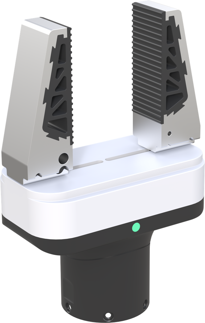
Dimensions and scale. Whole-machine dimensions 112 × 60 × 167 mm. Stroke 65 mm. Finger height 80 mm. Body weight 745 g. This row is about form factor or structural scale, used to check doors, elevators, tabletops, or transport; it is not operating height, nor reach. Do not add it to the vertical range. If the diagram shows protrusions, antennas, or a person's standing position that are not in this row, note separately that they are not part of the specification. If weight appears in an adjacent row, do not write it into the dimension sentence. Form factor is unrelated to alignment error. Doors, elevators, and transport only check the form factor; do not treat this row as operating height.
Operating range. The stroke of 65 mm is the finger opening and closing distance, not the robotic arm's reach, and not the body's vertical working range. This row describes the range the hand or lift can reach; the definition must follow the original wording: vertical working range, reach, motion radius, or stroke — these cannot be added together or renamed. If "excluding end-effector" is written, it must remain in the figure caption. When the original text does not mark a unit, retain the note "unit not specified"; do not delete it for tidiness. The range does not provide sampling timestamps. The figure caption retains the range definition from the original wording, as well as the phrases "excluding end-effector" or "unit not specified."
Motion. Open / close time 2 s. Position repeatability ±0.05 mm. The 2 seconds is the time for opening or closing, not the control frequency. This row describes how the ground or master arm moves. Four-wheel four-drive, differential drive, in-place rotation radius, and rotational speed are terms for different mechanisms and cannot be substituted for one another. A published speed is a capability, not a recommended teaching speed; teaching can be slower, but the slower speed is recorded in the experimental conditions, not written back as a specification. On pages that do not mention slope climbing or positioning, do not borrow from other pages. If both the chassis and the arm are recorded, they still need their own timestamps; do not assume they are already aligned. The teaching speed can be lower, but the lower speed is recorded in the conditions and does not change the published capability in this row.
Power supply. Rated voltage 24 V. Rated / maximum current 1.9 / 5.7 A. Rated / maximum power 45.6 / 136.8 W. There is no battery capacity and no runtime in hours. This row only retains the electrical terms that appear on the page: voltage, capacity, runtime, charging, current, or power. If there are no "hours," write that runtime is not given; do not fill in hours from an adjacent page. Do not rename charging time as runtime. Rated and maximum must be in separate columns. Retain "approximately" for approximate values. Do not sum the ampere-hours of multiple devices and call it one device's battery. The power-on time is not the master clock. Hours, charging, or current that do not appear remain not given; do not copy them from an adjacent page.
Perception and computing. Communication interface: 6-pin aviation connector. Communication protocol: RS485 / Modbus-RTU. Operating environment: 0–50 ℃, relative humidity ≤85%. There is no camera on the page. This line inventories the items already specified among sensors, computing, or communication, and retains the terms standard, included, optional, and selectable. Unchecked optional items do not count. When the cover conflicts with the checklist, cite the checklist, while not pretending the cover statement does not exist. Head-mounted devices and gloves do not belong in this line. Processors, hard drive capacity, or camera channel counts that are not written out should not be drawn into the system diagram. Cameras in the checklist, even if all open simultaneously, do not constitute a shared clock. Optional sensors that were not purchased do not enter this data dictionary.
End effector. It is itself the end effector. Whether it directly matches the flange, wiring harness, and protocol of the platform must be confirmed on the configuration sheet; the page states that it is not plug-and-play by default. This row describes which end the contact or gripping occurs at. Quick-change, compatible, and recommended are not models already included in the box. The finger-ring fixture on the main arm is not an end-effector gripper. Force, stroke, and load remain as-is in their respective rows and are not merged into a single system metric because they are mounted on a particular platform. Flange and protocol mappings that are not provided should be marked "to be confirmed," not "plug-and-play." The gripper's open/close timing must be marked separately and not merged into image frame numbers unless the synchronization sheet already specifies it. "Supports" or "compatible" without a model number cannot be treated as delivered.
Boundary. The standard quantity table for the lift model does not include this gripper. The folding model describes quick-change capability, not that the RMG22-65 is already in the box. The recommended item CTAG2F90-D is also not this model. This row is a boundary deliberately separated on the page: another model, another column, another product page, or an interface that still requires project confirmation after modularization. The boundary is not a defect note; it prevents verbally buying two pages as one. When writing the scheme, copy the boundary into "not included in this session." If a device not included is added later, open a new configuration sheet; do not go back and change the body name of old samples. The head-mounted device is not in this page's list, and even less should it be assumed to share a clock with this machine. Devices within the boundary must be ordered separately; do not rename old samples to say they already include it.
Configuration column. The order writes the model RMG22-65, and specifies which body it is mounted on, the quantity, and whether it replaces other gripper models in that body's recommended column. This row distinguishes standard, recommended, and optional. Recommended and optional items that are not checked are not delivered. When the standard row and the parameter table row disagree, keep both rows and use "locked for this session" to indicate which one is actually delivered, rather than crossing out one of the rows in the order without signing. Price and lead time are not written into this row's restatement. Sensors not purchased do not participate in the synchronization scheme. Unchecked recommended and optional items are written on the order as not delivered.
May be excerpted. Copy into the appendix on separate lines: envelope 5 kg; recommended friction load 2 kg; maximum gripping force 130 N; stroke 65 mm; finger height 80 mm; 745 g; open/close time 2 s; repeatability ±0.05 mm; 24 V; 1.9/5.7 A; 45.6/136.8 W; RS485 / Modbus-RTU. This is the type of line that can be pasted into the appendix: it has a subject, has units, and can be traced back to the original sentence on the product page. When pasting, retain words such as "approximately", "not included", "not specified", "optional", and "recommended". Do not convert and keep only the result. If the same number has different meanings on two pages, write it as two lines in the appendix. Do not mix test protocols into the specification excerpt. If the synchronization sheet cannot be written in six lines, fill in "not committed" in the synchronization column of the appendix. When pasting into the appendix, paste the words "approximately", "not included", "optional", etc. together with the values.
Do not write. Do not convert 130 N to 5 kg and then delete the original line. Do not write ±0.05 mm as the repeatability of the attached robotic arm. Do not write battery life. This line is a negative statement for review purposes. It does not describe what the device can do; it only prevents hours, degrees of freedom, load subjects, or cover slogans from adjacent pages from being written in. If a manuscript search hits this negative statement, revert to the original sentence on the product page; do not interpret it as "approximately". Success rates from external papers and total hours not published on this site likewise must not be written in. It is prohibited to write that PPS alignment with E6 or E2 has been completed, unless there is a separate written agreement. If a manuscript search hits this negative statement, revert to the original sentence on the product page.
| Projects | Public-Facing Positioning of This Page |
|---|---|
| Degrees of Freedom | This is an end-effector gripper, not a multi-joint arm. The public table does not give the gripper a "degree of freedom" integer; do not fabricate one to align with other platforms. |
| Load and Mass | Maximum envelope grasp payload 5 kg. Recommended maximum friction payload 2 kg. Maximum clamping force 130 N. These three numbers cannot all be written as the same 5. |
| Form Factor and Scale | Overall dimensions 112 × 60 × 167 mm. Stroke 65 mm. Finger height 80 mm. Body weight 745 g. |
| Operating Range | The 65 mm stroke is the finger opening distance, not the robotic arm reach, nor the platform's vertical working range. |
| Motion | Open / close time 2 s. Positional repeatability ±0.05 mm. The 2 seconds is the specification for the open or close time, not the control frequency. |
| Power | Rated voltage 24 V. Rated / maximum current 1.9 / 5.7 A. Rated / maximum power 45.6 / 136.8 W. No battery capacity, no battery life in hours. |
| Perception & Compute | Communication interface: 6-pin aviation connector. Communication protocol: RS485 / Modbus-RTU. Operating environment: 0–50 °C, relative humidity ≤85%. There is no camera on the page. |
| End Effector | It is itself the end-effector. Whether it directly matches the flange, wiring harness, and protocols of the platform must be confirmed on the configuration sheet; the page states that plug-and-play is not the default. |
| Boundary | The standard quantity table for the lift model does not include this gripper. The folding model lists quick-change capability, not that the RMG22-65 is already in the box. The recommended item CTAG2F90-D is also not this model. |
| Configuration Panel | The order should specify model RMG22-65, and state which platform it is mounted on, the quantity, and whether it replaces other gripper models listed in that platform's recommended column. |
| Excerptable | Attachment specifications listed line by line: envelope 5 kg; recommended friction 2 kg; maximum gripping force 130 N; stroke 65 mm; finger height 80 mm; 745 g; open/close time 2 s; repeatability ±0.05 mm; 24 V; 1.9/5.7 A; 45.6/136.8 W; RS485 / Modbus-RTU. |
| Do not write | Do not convert 130 N to 5 kg and then delete the original row. Do not write ±0.05 mm as the repeatability of the attached robotic arm. Do not state battery life. |
Relationship to Public Methods and Adjacent Pages
Pressing start on multiple devices at the same time does not mean the clocks are aligned. The head-mounted unit, master arm, slave arm, gripper, and chassis each have their own sampling clock. Without a common time base, it is impossible afterward to pair "the frame the human saw" with "the joint angles the arm actually reached" into a training sample. When frames are misaligned, the visuomotor policy learns misaligned causality.
The product page does not guarantee that the base unit and E6 or E2 have been synchronized via PPS plus serial port. The wrist camera and ring locator are accessories; powering them on together is not time synchronization. If a project requires synchronization, it must be listed separately in the configuration sheet: who is the master clock, what signal is used, the allowed alignment error, and how dropped frames are marked. If these sentences cannot be written, do not write "synchronized" in the proposal.
Do not mix sampling rates either. The control frequencies of the glove, head-mounted unit, and arm are not the same number. G7 is 120 Hz, G2-L transmits at 50 Hz, and E6 raw imagery can reach 60 Hz. The recording frequency of platform joints follows the actual controller and the written interface; do not invent a frequency that is not written on the page.
This article explains how timestamps should be required when this embodiment is listed alongside the head-mounted device and main arm, and which parts the page has not yet committed to.
Before handing off to a colleague
If the sync sheet has six blank rows, capture can still proceed, but the file name must include "clock not synchronized." Training scripts do not read directories with this marker by default. Do not backfill "it was aligned at the time" after capture ends. A misalignment value may only be used to execute a discard rule if it appears in a written protocol; without a protocol, keep the entire segment as unaligned raw data rather than cutting it into fragments that look continuous. The timestamp field names for head-mounted device, main arm, gripper, and embodiment are separated in advance to avoid overwriting by identical names. The read script for the clock-not-synchronized directory must have an assertion: refuse if the marker is not present in the path. Do not rely on human memory alone. The marker is written in two places: the directory name and the file header. The file header reads "no committed common clock." If a sync protocol is added later, new captures go into a new directory; old directories are not retroactively relabeled as aligned. Retroactive relabeling would make the misalignment at the time appear as though the later protocol had already taken effect.
First, lack of time synchronization must be written into the directory name and the file header.
Second, the script rejects misreadings that are not labeled.
Third, do not relabel as aligned after the fact.
Fourth, a new protocol only covers new directories.
Fifth, keep the timestamp field names of each device separate.
Sixth, without an agreement, do not cut segments into continuous samples.
Continue Reading
- 01 Task Boundaries
- 02 Specification Standards
- 03 Degrees of Freedom
- 04 Payload & Self-Weight
- 05 Workspace
- 06 Locomotion Method
- 07 Perception and Computing
- 08 Power Specifications
- 09 Data Recording
- 10 Time Alignment
- 11 End-Effector Boundaries
- 12 Site Constraints
- 13 Configuration Sheet
- 14 Three-Way Comparison
- 15 Literature References
- 16 Master-Slave Workstation
- 17 Acceptable Deliverable Statements
- 18 Prohibited Conflations
- 19 On-Site Deployment
- 20 Evaluation Path
Back to Product Center View this product page
This article was written on October 3, 2026, for selection and specification verification purposes. Device parameters are subject to the product page tables and do not constitute a supply commitment. External papers only illustrate how problems are framed in the industry; their success rates and data scales belong to the original authors' experiments and are not TOBI's measured results. Phone: +86 137 5502 0164.