Skip to content
TOBI
Skip to main content
Prototype / planned mass production information is subject to order confirmation

TOBI RING LOCATOR / INFRARED POSITIONING MODULE

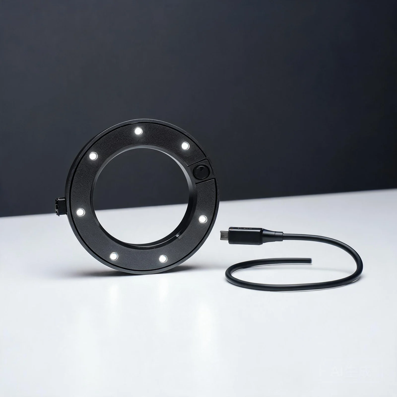
Light ring positioning module

The light ring positioning module is an infrared positioning peripheral designed for use with E6/E8 combinations. It integrates the positioning light ring, IMU, clock multiplexing interface, and gripper mounting structure into a single extensible node, helping teams incorporate external perception objects such as tools, grippers, or gloves into first-person capture projects.

Approx. 80gModule weight specifications
USB-CVBUS power supply
<1msExteroceptive synchronization materials
Real product photo of the TOBI light-ring positioning module mounted on a third-party gripper
Infrared light ringCombined positioning node
1kHzBuilt-in IMU (specs per version documentation)
UART / PPSClock Interface Reuse
No batteryVBUS power supply documentation
2026.09Planned mass production time

EXTERNAL SENSING NODE

Not a standalone localization system,
Not a standalone product, but a coordinate node within a combined solution.

The light-ring positioning module must be understood in conjunction with the combined E6 or E8 solution. The documentation statement "in the specified E6/E8 combined solution, it may be possible to evaluate reducing reliance on external positioning base stations" applies to that specific combined configuration; it does not indicate that this module is a universal product that can independently replace all external positioning systems.

COMBINATION TOPOLOGY

E6 / E8
+ Ring + Tool

Positioning information is collected by the light ring module and transmitted to the EGO device for storage. Compatibility range, mounting position, visibility, and task environment must be confirmed in the project.

Light-ring positioning module and third-party gripper mounting structure (official schematic)
01 / Infrared Positioning

Combined with E6/E8

Documentation indicates that positioning can be achieved in combination with E6/E8, and describes how the combined solution may reduce reliance on external positioning base stations in the specified E6/E8 configuration. Actual coverage and accuracy must be validated per scenario.

02 / Clock Connection

UART and PPS Multiplexing

For the version without ISP documentation, use the multiplexed connection definitions for UART_TX / UART_RX / PPS; interface pins, host version, and cabling scheme are confirmed per configuration.

03 / Motion Expansion

Integrated into Gripper or Glove

Can be integrated into third-party grippers and supports connecting external perception devices such as grippers and gloves. Mechanical mounting and environmental occlusion effects require project-level validation.

04 / Power and communication

VBUS power node

The documentation record has no built-in battery, one USB Type-C port, VBUS power supply, supports 2.4G and BLE; the final communication and power combination is subject to confirmation on the production version.

INTEGRATION DATA

First define the tool trajectory,
Then define the positioning solution.

The procurement value of the light ring module depends on the object to be tracked, how it is combined with the EGO host, visibility, clock, and data storage structure. The page presents combination capabilities and does not extend peripheral specifications into unverified standalone positioning performance.

Light ring pose information

The documentation states that light-ring pose information can be captured and transmitted to EGO for storage. The specific coordinate system, output format, update rate, and usable range must be confirmed through the project technical plan.

Stored in combination with the EGO host

IMU and synchronization

Built-in IMU (specifications per version documentation), documented stationary noise of 0.001rad/s. External perception device synchronization accuracy is documented as less than 1 ms, but no independent test report is included.

<1msData specification

Not an independent commitment

The current attachment does not provide test reports for independent positioning accuracy, spatial coverage, environmental interference, base-station-free operating range, or third-party gripper compatibility.

Based on combined testing

STATUS & BOUNDARY

First confirm the combined devices,
Then confirm peripheral delivery.

Documentation records that the light-ring positioning module was a prototype in August 2026, with mass production planned for September 2026. Status, combination compatibility, firmware, accessories, and actual data performance must all be confirmed during project evaluation and ordering.

PRODUCT STATUS

Planned mass production information

2026.09

This timeline comes from attached planning materials and does not constitute current in-stock availability, a confirmed delivery date, or a commitment to bulk delivery.

COMBINATION

Applicable to E6 / E8 Solutions

EGO

"In the specified E6/E8 combination solution, it is possible to evaluate reducing dependence on external positioning base stations" is the description of the E6/E8 combination solution in the documentation; specific equipment, installation, and environmental conditions should be included in the evaluation.

SYNCHRONIZATION

External perception time alignment

<1ms

Synchronization accuracy is based on documentation figures; no independent test samples, methods, or statistical reports are provided, and it cannot substitute for system-level on-site acceptance.

System Design Note:If you need usable trajectories for grippers, tools, or gloves, the EGO host, the number and mounting of light rings, clock/power, occlusion conditions, data coordinate system, output format, and test tasks should all be frozen during the evaluation phase.
Product Type
Infrared light ring positioning module; an external perception/positioning expansion used in combination with E6/E8.
Weight
Material weight approximately 80g.
IMU
Built-in IMU (specifications per version documentation); static noise floor of 0.001 rad/s.
Communications
Supports 2.4G and BLE; specific protocols, throughput, versions, and host compatibility range are confirmed per project.
Power and interfaces
USB Type-C ×1; no built-in battery; the version without ISP documentation is powered via VBUS, with UART_TX / UART_RX / PPS multiplexed connections.
Data
Light-ring pose information is transmitted to EGO for storage; coordinate frames, output format, update rate, and actual quality are subject to the combined solution.
Peripheral Integration
Can be integrated into third-party grippers; supports connection to external perception devices such as grippers/data gloves; mechanical compatibility and synchronization conditions require evaluation.
Status note: the materials record a prototype in August 2026 and planned mass production in September 2026. This page does not extend the planned status, the <1ms synchronization specification, or the combined positioning description into an unconditional independent positioning performance guarantee.

INTEGRATE BEFORE PROCURE

Let grippers and tools,
Enter a verifiable data acquisition plan.

The technical evaluation will confirm the combination solution around the EGO main unit, tracked objects, mechanical mounting, visibility, clocking, power supply, data format, and task samples. This process does not constitute an automatic quote, supply commitment, or system performance guarantee.

Confirm the E6/E8 host units, software/firmware, and number of light rings.
Confirm the tracked objects and mechanical mounting for grippers, tools, gloves, etc.
Confirm PPS/UART, USB-C power supply, communication, and data coordinate system.
Confirm prototype/mass-production status, test tasks, delivered accessories, and acceptance documents.

DATA & PROJECT READINESS

From specifications to an acceptable capture plan.From specifications to a testable capture setup.

Can it be used directly for robot training?Is this data ready for robot training?

Device observations do not automatically equal robot action labels. First confirm the data fields, timestamps, coordinate frames, target action space and data quality, then validate the conversion and training pipeline.Device observations are not automatically robot-action labels. Validate fields, timestamps, coordinate frames, target action space and quality before conversion and training.

How do I confirm supply and delivery scope?How do I confirm supply and scope?

Provide the task, quantity and planned delivery date. Confirm the device version, firmware, accessories, support scope and acceptance method in writing. Historical prototypes or production plans do not mean current stock is available.Provide the task, quantity and delivery window. Confirm the version, firmware, accessories, support and acceptance method in writing. Historical production plans do not confirm current stock.

How do I sync with other devices?How is cross-device synchronization verified?

Starting together does not mean clock synchronization. For a combined solution, confirm the clock source, interfaces, timestamp definitions, error statistics and dropped-frame handling; single-device metrics cannot substitute for full-system acceptance.Starting together is not clock synchronization. Confirm clock source, interfaces, timestamp definitions, error statistics and dropped-frame handling for the complete system.